
Introduction#
In the embedded world, firmware updates are essential and increasingly important. As IoT solutions grow exponentially in numbers and complexity, so does the concern to make devices secure and updatable in the field efficiently.
Some years ago, MCUboot emerged as an open source bootloader project for small and low-cost systems, designed to simplify and provide a standard in this field. It started as an Apache Mynewt subproject when developers decided to separate the bootloader from OS development. Later, it was ported to Zephyr RTOS and became its default bootloader.
Espressif Systems has been broadening support for additional third-party RTOSes such as Zephyr and NuttX, offering developers more choices for its SoCs. For this reason, a port for Espressif SoCs has been created within the MCUboot project.
This guide shows how to get started with MCUboot on your ESP32-based project.
This articles covers environment setup, required configuration in the application side, how to build the MCUboot Espressif Port bootloader and how to flash it into the device. The ESP32 DevKitC board was used to prepare this guide.
The MCUboot-compatible application mentioned in this guide can be either a NuttX RTOS application or a Zephyr RTOS application built for Espressif SoCs with MCUboot compatibility configuration enable.
This guide assumes that you are familiar with building and configuring the chosen RTOS.
What is MCUboot?#
MCUboot is an open source secure bootloader for 32-bit microcontrollers. The project defines a common infrastructure for secure boot and it mainly covers:
Fault-tolerant updates: MCUboot defines a clear flash layout. It uses slots to store the main bootable image and the update image in separate flash regions. A scratch area supports swapping images during firmware updates. This design ensures updates are reliable and allows MCUboot to recover or revert if any issues occur.
Security: MCUboot validates firmware images by checking hashes and verifying signatures using asymmetric key algorithms such as RSA 2048/3072, ECDSA, and ed25519. These mechanisms ensure the integrity and authenticity of the images.
The project aims to standardize these aspects comprehensively. MCUboot core features are independent from any operating system and hardware, relying on hardware porting layers from the target host OS.
Image and flash organization#
To track the general information, swap and update states from an application image, MCUboot requires specific data added by imgtool. This tool is provided within the MCUboot project and it formats the image binary adding the expected header and trailer, the signature, and can also generate signing keys.
MCUboot defines a flash organization where a flash area can contain multiple executable images depending on its boot and update configuration. Each image area contains two image slots: a primary and a secondary. By default, the bootloader only runs an image from the primary slot. The secondary slot is where an incoming image is staged prior to being installed; then its content will be either swapped to the primary slot or overwrote when updating.
We can identify four types of flash areas in the layout:
| AREA | ID | DESCRIPTION |
|---|---|---|
| Bootloader | 0 | Bootloader region (MCUboot) |
| Primary Slot | 1 | Main bootable image, code always runs from there |
| Secondary Slot | 2 | Staging area for firmware updates, it stores the incoming image and, after the swap, stores the original image to enable recovery if needed |
| Scratch | 3 | Temporary area used for helping the image swap when updating |
MCUboot also supports multiple images, allowing you to define additional image areas with their own primary and secondary slots.
For the MCUboot Espressif Port the layout information is stored in the <MCUBOOT_DIR>/boot/espressif/port/<ESP_SOC>/bootloader.conf file. Addresses and sizes can be modified, but the following rules must be followed:
- Bootloader address must be kept since it’s where the ROM bootloader looks for a valid Second Stage Bootloader to start.
- None of the slots must overlap.
- Primary and Secondary slots must be the same size.
- Scratch area must be large enough to store at least the largest flash sector that will be swapped.
- Both MCUboot and the application must be aware of this layout for correct operation.
High-level overview of the boot process#
The following diagram shows the basic boot execution flow:
flowchart TB
    %% Nodes
    A[Reset]
    B[Boot start]
    C[Bring-up]
    D[MCUboot routines]

    E{Is previous
swap in progress?}
    F[Finish swap]

    G{Check image
confirmation}

    H{Is Primary
slot valid?}
    X[Boot error,
halt]

    I{Is Secondary
slot valid?}
    J[Swap images]
    K[Erase secondary slot]

    L[Revert image]

    Z[Boot primary
slot image]

    %% Flow
    A --> B --> C --> D --> E

    E -- No --> G
    E -- Yes --> F --> Z

    G -- Confirmed --> H
    H -- No --> X
    H -- Yes --> Z

    G -- Swap requested --> I
    I -- Yes --> J --> Z
    I -- No --> K --> Z

    G -- Not confirmed --> L --> Z

    %% Styling
    classDef process fill:#efe7ff,stroke:#7b5cff,stroke-width:2px,color:#000
    classDef decision fill:#fff3c4,stroke:#c9a227,stroke-width:2px,color:#000
    classDef success fill:#d6f5d6,stroke:#2e8b57,stroke-width:2px,color:#000
    classDef error fill:#f7c6c6,stroke:#c0392b,stroke-width:2px,color:#000

    %% Class assignments
    class A,B,C,D,F,J,K,L process
    class E,G,H,I decision
    class Z success
    class X error
Notice that the bootloader verifies both slots in the process, but only boots the image from the Primary Slot:
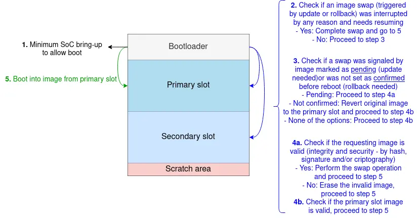
MCUboot boot process overview
Setting the environment#
First, prepare the development environment. This guide assumes the use of Linux (Ubuntu 20.04.2 LTS or later).
Ensure you have git, Python3, pip, CMake and Ninja installed. If you don’t, you can run the following (this step is optional):
sudo apt update
sudo apt upgrade
sudo apt install git python3 python3-pip cmake ninja-build
MCUboot Espressif Port HAL#
The MCUboot Espressif Port relies on HAL (Hardware Abstraction Layer) sources provided by ESP-IDF. You must either have ESP-IDF installed, which allows building the project standalone, or use one of Espressif’s HAL sources available for Zephyr (zephyrproject-rtos/hal_espressif/) or NuttX (espressif/esp-hal-3rdparty). For the latter options, it is recommended to use them only within their respective RTOS build systems, as the source revisions may not match the expected versions.
Installing ESP-IDF v5.1.6
git clone --recursive https://github.com/espressif/esp-idf.git
cd <IDF_PATH>
git checkout v5.1.6
<IDF_PATH>/install.sh
. <IDF_PATH>/export.sh
More information about ESP-IDF installation can be found here.
Clone and set up MCUboot#
Clone the repository into a directory of your choice (other than ESP-IDF installation):
git clone https://github.com/mcu-tools/mcuboot.git
cd mcuboot
Install the additional dependencies needed by MCUboot:
pip3 install -r scripts/requirements.txtUpdate the MbedTLS submodule required by MCUboot:
git submodule update --init --recursive ext/mbedtlsAny images you plan to boot with MCUboot must be formatted and signed using
imgtool. You can findimgtoolat<MCUBOOT_DIR>/scripts/imgtool.py(where<MCUBOOT_DIR>is the path to the cloned repository), or optionally, you can install it as follows:pip3 install imgtool
Building and flashing MCUboot on ESP32#
With everything set, let’s configure, build and flash the MCUboot Espressif Port bootloader.
Firstly set the flash layout organization in the
<MCUBOOT_DIR>/boot/espressif/port/esp32/bootloader.conffile, it must match the same flash organization as the chosen RTOS. For example:CONFIG_ESP_FLASH_SIZE=4MB CONFIG_ESP_BOOTLOADER_SIZE=0xF000 CONFIG_ESP_BOOTLOADER_OFFSET=0x1000 CONFIG_ESP_IMAGE0_PRIMARY_START_ADDRESS=0x20000 CONFIG_ESP_APPLICATION_SIZE=0x150000 CONFIG_ESP_IMAGE0_SECONDARY_START_ADDRESS=0x170000 CONFIG_ESP_SCRATCH_OFFSET=0x3E0000 CONFIG_ESP_SCRATCH_SIZE=0x1F000Compile and generate the ELF:
cd <MCUBOOT_DIR>/boot/espressif
cmake -DCMAKE_TOOLCHAIN_FILE=tools/toolchain-esp32.cmake -DMCUBOOT_TARGET=esp32 -DESP_HAL_PATH=<IDF_PATH> -DMCUBOOT_FLASH_PORT=/dev/ttyUSB0 -B build -GNinja
ninja -C build/Erase the device’s flash:
esptool.py -p <PORT> erase_flashFlash MCUboot Espressif Port bootloader to your board:
ninja -C build/ flashAlternatively:
esptool.py -p /dev/ttyUSB0 -b 921600 --before default_reset --after hard_reset --chip esp32 write_flash --flash_mode dio --flash_size detect --flash_freq 40m 0x1000 build/mcuboot_esp32.bin
-p /dev/ttyUSB0) and baud rate (-b 921600) according to your board connection.Check the serial monitor on the UART port (the same port used to flash) and reset your ESP32 board. This guide uses
picocomtool, but any serial monitor tool can be used:picocom -b 115200 /dev/ttyUSB0
Since no image has been flashed yet, you will see MCUboot waiting for an application image in the primary slot.
[esp32] [INF] *** Booting MCUboot build v2.3.0-rc2-3-g234c66e6 ***
[esp32] [INF] [boot] chip revision: v3.0
[esp32] [INF] [boot.esp32] SPI Speed      : 40MHz
[esp32] [INF] [boot.esp32] SPI Mode       : DIO
[esp32] [INF] [boot.esp32] SPI Flash Size : 4MB
[esp32] [INF] [boot] Enabling RNG early entropy source...
[esp32] [INF] Primary image: magic=unset, swap_type=0x1, copy_done=0x3, image_ok=0x3
[esp32] [INF] Scratch: magic=unset, swap_type=0x1, copy_done=0x3, image_ok=0x3
[esp32] [INF] Boot source: primary slot
[esp32] [INF] Image index: 0, Swap type: none
[esp32] [ERR] Unable to find bootable image
Preparing and flashing an application#
You can use applications from either Zephyr or NuttX, ensuring MCUboot compatibility is enabled in whichever RTOS you use.
This section briefly outlines the required Kconfigs for configuring a NuttX or Zephyr application for MCUboot compatibility. It assumes you are already familiar with building and configuring your chosen RTOS.
NuttX RTOS#
Set the menuconfig options:
- Enable the
CONFIG_ESP32_APP_FORMAT_MCUBOOToption - Match the
SPI Flash Configurationwith the slots configuration in<MCUBOOT_DIR>/boot/espressif/port/esp32/bootloader.conf
In this guide’s example, menuconfig was set as follows:
- System Type -> Bootloader and Image Configuration->
- Enable MCUboot-bootable format (
CONFIG_ESP32_APP_FORMAT_MCUBOOT): y
- Enable MCUboot-bootable format (
- System Type -> SPI Flash Configuration ->
- Application image primary slot offset (
CONFIG_ESP32_OTA_PRIMARY_SLOT_OFFSET): 0x20000 - Application image secondary slot offset (
CONFIG_ESP32_OTA_SECONDARY_SLOT_OFFSET): 0x170000 - Application image slot size (in bytes) (
CONFIG_ESP32_OTA_SLOT_SIZE): 0x150000 - Scratch partition offset (
CONFIG_ESP32_OTA_SCRATCH_OFFSET): 0x3E0000 - Scratch partition size (
CONFIG_ESP32_OTA_SCRATCH_SIZE): 0x1F000
- Application image primary slot offset (
Zephyr RTOS#
Enable the CONFIG_BOOTLOADER_MCUBOOT configuration and check if the flash partitions on the DTS from your board matches what was set in the <MCUBOOT_DIR>/boot/espressif/port/esp32/bootloader.conf. For this example it is possible to set an overlay file with the following content:
&flash0 {
	partitions {
		boot_partition: partition@0 {
			label = "mcuboot";
			reg = <0x0 DT_SIZE_K(64)>;
		};

		slot0_partition: partition@20000 {
			label = "image-0";
			reg = <0x20000 DT_SIZE_K(1344)>;
		};

		slot1_partition: partition@170000 {
			label = "image-1";
			reg = <0x170000 DT_SIZE_K(1344)>;
		};

		storage_partition: partition@3b0000 {
			label = "storage";
			reg = <0x3B0000 DT_SIZE_K(192)>;
		};

		scratch_partition: partition@3e0000 {
			label = "image-scratch";
			reg = <0x3E0000 DT_SIZE_K(124)>;
		};
	};
};
Signing and Flashing the Application#
Before flashing, sign the application binary using scripts/imgtool.py with python3. Replace <APP_BIN> with your application binary (e.g., nuttx.hex or zephyr.bin), and signed.bin will be the output signed image:
python3 scripts/imgtool.py sign --align 4 -v 0 -H 32 --pad-header -S 0x00150000 <APP_BIN> signed.bin
Alternatively, using imgtool (if you installed imgtool through pip):
imgtool sign --align 4 -v 0 -H 32 --pad-header -S 0x00150000 <APP_BIN> signed.bin
--pad-header parameter.Here is a quick look on what these imgtool sign parameters do:
--align 4: Specify the flash device alignment as 4 bytes (32-bit word).-v 0: Specify the image version (in this case,0).-H 32: Specify the MCUboot header size to be added to the image binary.--pad-header: Indicates toimgtoolto add the MCUboot header into the beginning of the image binary, instead of overwritting it (the Zephyr build for some platforms already pads the binary beginning with 0s and may not need this parameter).-S 0x00150000: Indicates the slot size so the tool can add the MCUboot trailer properly.
Flash the signed image to the device at the primary slot address:
esptool.py -p /dev/ttyUSB0 -b 921600 --before default_reset --after hard_reset --chip esp32 write_flash --flash_mode dio --flash_size detect --flash_freq 40m 0x20000 signed.bin
Checking the serial monitor, MCUboot should now successfully load and boot the application from the primary slot.
NuttX’s nsh:
[esp32] [INF] *** Booting MCUboot build v2.3.0-rc2-3-g234c66e6 ***
[esp32] [INF] [boot] chip revision: v3.0
[esp32] [INF] [boot.esp32] SPI Speed      : 40MHz
[esp32] [INF] [boot.esp32] SPI Mode       : DIO
[esp32] [INF] [boot.esp32] SPI Flash Size : 4MB
[esp32] [INF] [boot] Enabling RNG early entropy source...
[esp32] [INF] Primary image: magic=unset, swap_type=0x1, copy_done=0x3, image_ok=0x3
[esp32] [INF] Scratch: magic=unset, swap_type=0x1, copy_done=0x3, image_ok=0x3
[esp32] [INF] Boot source: primary slot
[esp32] [INF] Image index: 0, Swap type: none
[esp32] [INF] Disabling RNG early entropy source...
[esp32] [INF] br_image_off = 0x20000
[esp32] [INF] ih_hdr_size = 0x20
[esp32] [INF] Loading image 0 - slot 0 from flash, area id: 1
[esp32] [INF] DRAM segment: start=0x250a4, size=0xce4, vaddr=0x3ffb2010
[esp32] [INF] IRAM segment: start=0x20080, size=0x5024, vaddr=0x40080000
[esp32] [INF] start=0x40082048
IROM segment aligned lma 0x00040000 vma 0x400d0000 len 0x012afc (76540)
DROM segment aligned lma 0x00030000 vma 0x3f410000 len 0x003060 (12384)

NuttShell (NSH) NuttX-10.4.0
nsh>
Zephyr’s hello world:
[esp32] [INF] *** Booting MCUboot build v2.3.0-rc2-3-g234c66e6 ***
[esp32] [INF] [boot] chip revision: v3.0
[esp32] [INF] [boot.esp32] SPI Speed      : 40MHz
[esp32] [INF] [boot.esp32] SPI Mode       : DIO
[esp32] [INF] [boot.esp32] SPI Flash Size : 4MB
[esp32] [INF] [boot] Enabling RNG early entropy source...
[esp32] [INF] Primary image: magic=unset, swap_type=0x1, copy_done=0x3, image_ok=0x3
[esp32] [INF] Scratch: magic=unset, swap_type=0x1, copy_done=0x3, image_ok=0x3
[esp32] [INF] Boot source: primary slot
[esp32] [INF] Image index: 0, Swap type: none
[esp32] [INF] Disabling RNG early entropy source...
[esp32] [INF] br_image_off = 0x20000
[esp32] [INF] ih_hdr_size = 0x20
[esp32] [INF] Loading image 0 - slot 0 from flash, area id: 1
[esp32] [INF] DRAM segment: start=0x25f10, size=0x1110, vaddr=0x3ffb0000
[esp32] [INF] IRAM segment: start=0x20080, size=0x5e90, vaddr=0x40080000
[esp32] [INF] start=0x400830e0
I (327) boot: IROM      : lma=00040000h vma=400d0000h size=036D8h ( 14040) map
I (327) boot: DROM      : lma=00030000h vma=3f400000h size=00E94h (  3732) map
I (343) boot: libc heap size 182 kB.
I (343) spi_flash: detected chip: generic
I (343) spi_flash: flash io: dio
*** Booting Zephyr OS build v4.3.0-rc2-65-g03ce83a18fd5 ***
Hello World! esp32_devkitc/esp32/procpu
Conclusion#
MCUboot provides a solid structure and defines a standard flow for firmware updates and secure boot. These features are already implemented in the bootloader and can be easily enabled without many modifications when developing firmware.
Furthermore, as an open source project, MCUboot benefits from development by an interested and diverse community, resulting in faster issue resolution and active development.
In this guide, we covered how to build MCUboot bootloader for ESP32, how to sign an image, and how to organize flash properly. For more detailed information, refer to the official MCUboot documentation.
The next step for this series is to understand how updates work in the MCUboot and use this feature appropriately.